Product idea
More than twenty years ago, Mr.Polato was a passionate pilot of motor-deltaplane and, in the meantime, He was also professional “ scientist” in the applicative development of advanced materials for industrial use.
At that time, the propeller for Ultralight Flight was made in wood, with the advantages and the limitations that are typical of this natural material. For this reason and according to his professional experience, he outlined that, by using composite materials in place of wood, he should be able to produce propellers with some features clearly greater than the existing.
At that very moment, a wide and methodical experimental project was started. As matter of the project, different composite techniques and several materials were studied.
Objective of the project was to produce the propeller blade with the following targets:
·
absolute structural reliability
·
greatest lightness
·
greatest power yield
·
greatest functional reliability
The experimentation led to the definition of the moulding technology for the production of a super-light blade having the feature of united body and without junction lines along attack and leading edge. The interior of the blade is made of expanded material foam. The covering of the blade is in composite material made by (continuous fibre + fibre tissue + resin). The thickness of the composite layer is sized proportional to the stress field acting on the blade during under operation. In such way the mechanical strength of the carrying structure with the lightness of the entire blade.
The power yield is obtained by careful study of blade profiles and fine experimental test.
he functional reliability of the entire propeller is assured by precise processing of mechanical hub and interior parts, realized by numeric control station.
Each component in the hub is made by its proper metallic alloy selected on the basis of its structural/functional role and of the mechanical stress acting during the propeller operation.
Design and material selection
We design of the propeller must start from mechanical and technological items. The shape and the operation of the propeller are “aerodynamic” items and are studied as described here below.
The mechanical and structural design starts with the constructive idea. In particular, with the propeller, the target of this idea is to obtain the greatest characteristics in strenght and reliability with the lowest material weight.
The fp idea is to employ structural solutions having straight geometry and assuring the greatest reliabilty in each direction. In a second step, the body shape of the blade is realized on the supporting structure. For this reason, all the solutions concerning materials and constructive technology useful for the target must be identified.
Taking into account the market size, the technology should be tailored for small scale production, with possibility of scale expansion without other research investement. The cost will be a secondary factor and will be depending from the techniques identified.
In all these steps, the selection of the material for the construction of the blade is crucial. The reason being the propeller blades are subject to several stresses of high intensity, all them due to the centrifugal force during the operation.
Taking into account the several materials that could be used on the basis of their characteristics in relation to the main applicative needs, each of them exibits points of strenght and points of weakness.
In the table below we can have a first and rough qualitative comparison:
|
|
material
|
|
|
|
|
|
wood
|
composite
|
aluminium
|
steel
|
|
|
____________________________________________________
|
|||
|
characteristic
|
|
|
|
|
|
strength/weight
|
OOO
|
OOOOO
|
OO
|
O
|
|
dimensional stability
|
O
|
OOO
|
OOO
|
OOOO
|
|
fatigue resistance
|
OOOO
|
OOOO
|
OOOO
|
OOOO
|
|
machinability precision
|
O
|
OO
|
OOO
|
OOOOO
|
|
production cycle
|
OOOO
|
OOO
|
OO
|
O
|
The graded list is measured from the number of (o) being the best quoted (ooooo) and the worst quoted (o). Of course, for the real graded list needed from the designer, the table is to be filled with the experimental numbers of the measured characteristics.
In the above table, the list of characteristics is in order of importance.
It follows that wood is the first material we can consider as easy to machine and light. This explains the reason why the fixed pitch propeller is so diffused from the beginning of the flight age.
In a different grading, by considering firstly the lightness and the dimensional stability, the winning material is the composite. As we know, the composite is a technological product (not natural). More in detail, it can be defined as a structured combination of high strength fibres and bonding resin. This combination can be also of limited density.
Of course, different constraints are to be used for the blades in comparison to the hub. With regards of the hub’s requirements, the first is the mechanical precision of the blade rotation mechanism, which lies above the concept of lightness.
By using mono-oriented fibres we can obtain composite materials that have specific strength which is higher than any other material.
The first constraint to the use of composite materials is represented by the technological cost. In facts, if interesting results are obtained in comparison to other materials, the designing and the production technology must be developed by skilled people.
Aluminium is the third material in order of interest for its higher density. Steel is the last for the same reason.
According to the table above, we can outline that aluminium is to be preferred for the hub because of (lower density + machining precision). Moreover, the anchorage of the blade to the hub could be made by aluminium because of its lower density but, in practice, steel is to be preferred for its greater homogeneity and material reliability.
By summarizing the different items and considerations we can obtain the best solution of material for the different components of the propeller.
|
|
material
|
|
|
|
|
|
wood
|
composite
|
aluminium
|
steel
|
|
|
____________________________________________________
|
|||
|
propeller part
|
|
|
|
|
|
blade
|
OO
|
OOOO
|
|
|
|
body of the hub
|
|
|
OOOO
|
OO
|
|
blade shank
|
|
|
OOO
|
OOOO
|
As shown in this second table, each main part of the propeller can be made by two different materials, one of them being more advantageous. Following this guideline, we can define the optimal propeller as the combination of the most advantageous solutions. In conclusion, the optimal propeller should be made as follows:
- blade in composite
- hub in aluminium
- blade shank in steel
Of course, we must keep in mind that each material includes a wide family of different types. In second approximation, the choice of materials must find, for each part, the specific type by which tha material advantage is the greatest. This second analisys is not reported here. Moreover, the material’s choice is made on the base of all the caracteristics, also included the cost.
Structural solutions
The possible structural solutions are numerous. When we start from structural reliability as first target, the variable pitch propeller will have the following main requirements:
· strenght much higher to the highest operation stress, measured by high safety factor
· fatigue resistance for long operation life, measured by TBO
· accurate pitch variation, quick and with low effort, measured by degree/second
· pitch control simple and safe
Furthermore we need to remember that all of the above is always to be obtained with the lowest weigth and the lowes cost. Following this logic, the construction of the blade is determinative for the rest of the propeller construction. In effect, the use of composite materials allows to place the stress resistant material according to the field of stresses, in direction and amount. In this way, we can realize a blade with a very light tip and via-via heavier going to the stem, close to the hub, according to the growing trend of the stress field. In the interior, the blade could be empty. In practice, with composite materials, the stiffer structure for the same weigth is obtained by a very low density interior body (foam or other cellular material) and a thin composite covering.
The structural designing phase defines the distribution of the carrying structure in the different blade zones and calculate the amount needed.
In terms of method, in order to minimize the weigth, fp calculates the wall thickness starting from the blade tip and define the carrying material (fibre) needed to sustain the external part and the effect of the centrifugal force during rotation. All the calculation is developed by assuming the safety factor 10 referred to the greatest stressesacting on the blade and on the metallic parts of the hub, included stem and ball-bearings. It follows that all the components are working below 1/10 of their strenght. This safety level is of foundamental importance for the long life of the propeller, according to the experimental engineering.
Finally, a special feature. The shape of the blade makes the construction by composite material more laborious as lighter as we need it. At the beginning, some people were producing the blade by stratifying the two surfaces separately, each on its mould side. Then, the two shells were glued in order to realize the blade. However, it was not considered the fact the glue line is a weakness line because of the low mechanical characteristics of the glue, very poor in comparison to that of the fiber reinforced resin (=composite). As a conseguence, the “two shell” structure gave some problems like, for example, the opening of the blade along the glue line during operation.
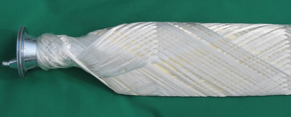
The solution to this weakness is obtained by the blade with unique structure, where the composite layer is wrapping the blade section continuosly, without glue lines along the attack and/or the leading edge.
As design concept, the structure of the fp blade is obtained by an interior foam core and the composite layer wrapping around the foam as shown. The composite layer is the carrying structure.
It is noted that, for the construction of the blade, glass fiber or carbon fiber can be used. Comparing the result that can be obtained with the two materials, it is found that carbon allows to obtain a more rigid and lighter blade, with a higher mechanical safety factor. For the resistance to delamination, which could be the only weak point of the carbon fiber, the problem does not exist due to the tubular structure of the integral winding construction.